Sunday, October 19, 2014

Day 98 - Eyestalk

I got inspired to work on the Plastruct disks that I had bought, and to see what kind of further progress I could make on the eye and eyestalk.  First, I needed to make a simple jig with each of the disks measured out on it and four flat nails to dissuade the disk from wandering while being drilled.  This way I could make sure I drilled in the center each time.  I decided to use a 3/8" forstner bit for cutting the disks after practicing first on a spare bit of acrylic.  Even with the jig, there was a small amount of eye-balling I needed to do make sure that the bit didn't wander too far off-center while tapping.

After the largest of the disks was done, I hammered in another set of nails for the next size down.  After drilling those, I repeated that for the smallest of the disks.  After all six disks were drilled, I also drilled the same sized hole into the back of the eye I had made previously.

I cut a small length off of my 3/8" threaded lamp rod and secured a disk onto it using two nuts above and one below.  I made sure that these were very snug (worrying a bit that I might crack the plastic) so that nothing came loose while the drill was spinning.  I put the lamp rod into the chuck of my drill press and proceeded to use a variety of methods to trim off the excess plastic that I didn't need.

Gently pressing down on a sheet of 80-grit sandpaper worked for a bit, but soon the plastic heated up and got somewhat soft.  I turned off the drill and waited for the disk to cool.  After that, I tried a hacksaw blade, and that seemed to work much better.  While the disk was spinning, I placed the hacksaw blade under it teeth upwards, and gently scraped it along the bottom of the disk, frequently checking the diameter with my calipers to make sure I was adhering to the plans.  After several minutes, I had trimmed off all that I needed.  I repeated this for the remaining disks, getting faster with each one.

After that, each disk was scuffed using steel wool and a 320-grit sandpaper sponge to get a nice frosted effect.  A quick spacing check using the aluminum I had previously cut seemed pretty satisfactory to me.  I then set these aside for a bit.

Back when I was making the inner gunbox assemblies, I kept the two 1/2" thick MDF circle offcuts my hole saw had made.  These, along with two circles of my thinner HDF board, were the 3.6cm thickness I needed for the eyestalk pivot.  I glued and clamped these together, and they're curing as I type.  Later, I will sand it smooth and drill a hole to accommodate the lamp rod.  It's just shy of the 10cm diameter needed, but the outer ribbed detailing I'll add to it should make it just the right size.

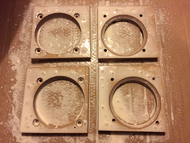
In order to make the optical illusion that the eyestalk consists of a single piece of metal, I needed to think outside the box a bit.  I have 3/8" threaded lamp rod to run the eventual wires through, but the thickness of the actual eyestalk is one inch.  This means I need to have layers built up around the rod.  Several weeks ago, I looked and looked for anything that would let me make nice, snug layers for the eyestalk, but the only thing I could find was some 3/4" PVC pipe.  It fit fairly well inside the 1" aluminum tubing that I have, but it still rattled around a bit.  Further, the threaded rod was much smaller than the PVC's inside diameter.

One day while looking for the very nuts that I used above to secure the disks onto the threaded rod, a thought struck me.  These nuts looked about the same size at the inner diameter of the PVC pipe.  A quick experiment showed me that I could fit the PVC over the nuts quite snugly, and that the whole assembly was nice and centered.

I made sections of PVC that were slightly shorter than the aluminum that will surround them (to accommodate the curvature of the eye disks once assembled).  To make the aluminum fit more snugly, I added a layer of trimmed duct tape to the PVC.

Then, I took two of the nuts and spun them way down the threaded lamp rod.  The longest piece of PVC covered them, one at each end to keep it centered.  Then I surrounded it with its aluminum part, slid an eyestalk disk down on top of that, then another nut/PVC/aluminum bit, another eyestalk disk, etc, etc, etc.

Before too long, I had finished it all off by placing the eye onto the rod, and securing it in place with a wide washer and a nut.  I was particularly pleased with how even and centered the eye disks were, keeping the illusion of one solid piece of tubing.

Now I just need to wait for my LED to arrive so that I can start with all the inner eye pieces, and get this bad boy lit up!

Monday, October 13, 2014

Day 96 and 97 - Dome cowl

I finally decided to stop being afraid of the dome cowl and actually finally make it.  I set out and bought a few more fiberglass supplies from TAP Plastic, then began cutting up pieces of cloth for the angled sections inside the mold.

I waxed the interior of the mold several times and let that sit for a bit. Then I applied a layer of PVA and let that dry.  Finally, I dusted a few coats of silicon mold release.  I wanted to make sure I had plenty of release layers between the mold and the final part!

After a little more time, I mixed up about 3oz of gel-coat and spread that on with a brush.  As it is getting colder, I added the maximum recommended amount for the catalyst.  I let the gel-coat sit for about three hours until it was only just slightly tacky, mostly dry.

I took some fiberglass strands that I pulled off of some woven cloth and placed that in the small trench in the top of the mold.  I was really afraid of having air bubbles in this little section, so I made sure to reinforce it as much as I could.

Then I placed the rest of the cur pieces in their positions, mixed up about 4oz of resin, and started brushing it on.  These cut sections didn't really overlap each other, so I then took some thin torn-up surfacing veil and applied some overlap.  Then I applied a heavy layer of overlapping chop mat on top of all that, with another 5oz of resin sealing it into place.  I rolled the mold all around in my hands while the resin started to set.  Once I no longer saw movement of the liquid, I sat it down and waited for it to cure.

The next day, I attempted to separate the part from the mold.  I have read many stories on how difficult it is to remove a cowl, but I didn't want to resort to cutting the mold into two pieces.  I placed putty wedges in similar to how I separated the dome from its mold.  On the bottom of the mold, however, I placed too many, and the cowl started to crack and split slightly.  Panicked, I removed all the wedges and decided upon a different strategy.

All around the mold, I put in one wedge, and then a second on top of it.  I then hammered in a wooden stir-stick in between the two wedges.  The stick always went in quite a bit further, so they were clearing the beveled edge of the cowl.  I repeated this this all around the cowl.

I poured in some boiling-hot water between the cowl and the mold, and eventually the two parts separated!  I quickly washed off the cowl and took a closer look at it.

The split in the middle was the most obvious.  It's going to need to be Bondo'd up a bit to conceal that.  But that's okay, because I also noticed that I had totally forgotten to place an indent in the mold for the recessed ID tag area!  When I Bondo this part, I'll be sure to include the ID tag indentation.  There was also an air pocket in one of the four corners; again, totally repairable.

I was especially happy with how well the detailing turned out on the top of the cowl!  This was the part I thought would be the most mangled.  But it's great!

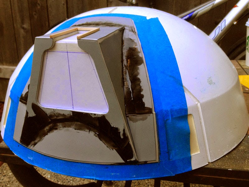
I took my Dremel tool and cut/ground the hole in the cowl where the eventual eyestalk will be, and temporarily attached the cowl to the dome for a quick photo op!

Next steps: Repair the cowl and put the ID tag indentation in place, then sand the whole thing because all the ripply roughness of the mold transferred to the cowl.

Sunday, September 28, 2014

Day 95 - The light cages and the eye

I spent a productive day working on the light cages and the eye piece.  Back in February of this year (2014), my plastic parts from Plastruct were delivered to me.  Prior to that, in November of 2013, I had a local maker shop laser-cut the parts for the light cages.  Assembling these was another task I was afraid to tackle, mainly because of the cost of the ABS plastic, and the cost of the laser-cut acrylic.  In addition, I had no back-up pieces in case I screwed up.  I hadn't ordered any glue from Plastruct, either, so I didn't have a means of gluing them together.


I had, however, obtained acrylic cement from TAP Plastics, and so I started there, with the light cages.  First, I drew a square, with the sides being the same as the diameter of the bottom part of the light cage.  I drew diagonals to find the location where the light cage struts were to be cemented, and lightly scored the acrylic with my box cutter blade.

Afterward, it was essentially a breeze to cement everything together.  The cement applicator has a needle nose, and, while holding the strut to be glued in place with one hand, I gently dragged the needle along the base.  The capillary action of the cement allowed it to draw itself directly under the piece.  After holding it in place for several seconds, a secure bond had formed.  I repeated this for all the remaining pieces, and eventually, I had to lovely (unpainted) light cages assembled!  In 24 to 48 hours, the molecular bond of the welded pieces will reach maximum strength.
(Of course, I would prefer to have aluminum light cages, but so far it's been prohibitively expensive for me to do that.  Maybe someday!)

Next up: Cutting up the stepped cone for Rainier's eye.  I took the smaller of the long tubes and sat it in the cone to find where I was going to cut it.  I marked out the spot and made a test cut one step higher for practice.  It wasn't too difficult of a job; I mainly just gently scraped the razor along the "L" of the step, over and over again until it was free.  Then I repeated that on the marked line once I was confident.

The resulting piece needed to be cut into two sections.  I again marked the places that needed to be cut, and soon I had both pieces ready to assemble.

I also needed to get the tubular sections of the eye piece cut to length per the plans, so I used my miter saw to do that on both the small tube and slightly larger one.  The miter saw wasn't my first choice for this, but I didn't have a miter box for a handheld saw.  Very carefully, I cut until I couldn't lower the saw further, then rotated the tube, continued the cut, and soon the job was done.  Some light sanding using 120-grit paper, and I had the pieces I needed.

Now, how was I going to glue all of this together?  I went to the web and googled what the proper bonding agent for ABS plastic was.  I ran across several videos where people demonstrated making their own glue using acetone and scrap pieces of ABS.  Eureka! I thought, and decided to give it a try.  Heck, it made sense to me—use ABS as a means to weld other ABS together.

First, I chopped up the scrap rings from the cone I had cut, and threw them in a jar.  I added a small amount of acetone to it, screwed on the lid, and let it sit for about an hour.  When I came back to check on it, it was all pretty much melted.  I gave it a good stir with a stick, and was very satisfied with the consistency.

After flipping over the two front eye pieces and placing them in their final position, I took a cotton swab, dipped it into the goo, and ran it along the edge of the seam.  I made sure a good amount of the slurry covered the piece.  Then I let that sit for about 30 minutes or so.  I was very pleased.  It was still slightly malleable, but, like the acrylic cement, it should be nice a solid once the acetone has completely evaporated.  I then added my glue to the edge of the smaller tube, and pressed the eye front onto it.  I repeated this for the larger tube edge, and squeezed the back eye hemisphere onto that.

Now they're both curing, so I'm going to give them all the time they need to dry.  Later, I might add another layer to the front piece and to the interior joins of both the tubes, just to make sure everything is nice and secure.

Thursday, September 25, 2014

Day 94 - Gunbox interior assemblies

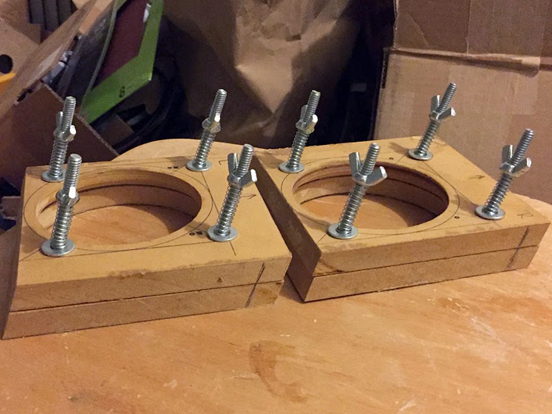
Again, following the path AdamSt paved, I have been working on a job that I've put off until now—the gunbox interior assemblies which keep the gun and plunger arm in position within the shoulder section.  Since nothing is currently holding the globes in place (except gravity), the approach is to "sandwich" them in using MDF plates, bolts, springs, and wing nuts.  The front of the gunbox (the exposed part on the shoulder section) can't be marred with the bolt holes, so similarly-shaped internal plates need to be made and installed.


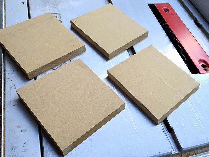
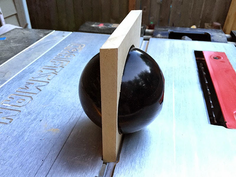
I couldn't find my protractor, so I went back into my own build diary to see if I had logged the front angle of the gunboxes, and I thankfully had done that.  It has a 20° angle, so I set my table saw blade accordingly and cut four pieces of 1/2" MDF to match, two per gunbox.  One of these will be attached via wood screws onto the interior of the gunbox as the middle part of the "sandwich", and the other will be the back.

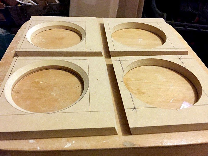
Now, I should have made these assemblies at the same time as the gunboxes themselves, because getting the exact measurements of the interior was a bit tricky since they're now part of the shoulder section proper.  As such, I cut the plates with a larger initial width, then trimmed them until they fit in each gunbox.  I then took a pencil and ran it along the edge of the gunbox holes, tracing a rough circle onto the two "middle" plates.  This was so that I knew the approximate location for where to drill with my 4" hole saw.  I traced an accurate 4" circle on top of that and drew a square around it to find the center.  Then I cut holes in both the left and right plates.

Not an exact science by any means!  I checked my work thus far by seeing if the globes would pass through the 4" hole untouched (the middle plate doesn't hold the globes in place, that's the back plate's job).  I also checked to see if the holes lines up with each other, and if the 20° angle was accurate for the slant.  The globe still poked out of the gunbox unobstructed.  Success!


Next, I lined up the back plate to the middle plate, and traced around the 4" hole that I just drilled.  I repeated my process for finding the center of the circle.  Now, since this back plate will be butted up against the other side of the globe, the hole needs to be smaller.  I switched from my 4" saw to my 3.5" one and cut those holes.  Like the front of the gunbox, it needed to have a 45° chamfer.  Switching to my hand router, I added that detail.

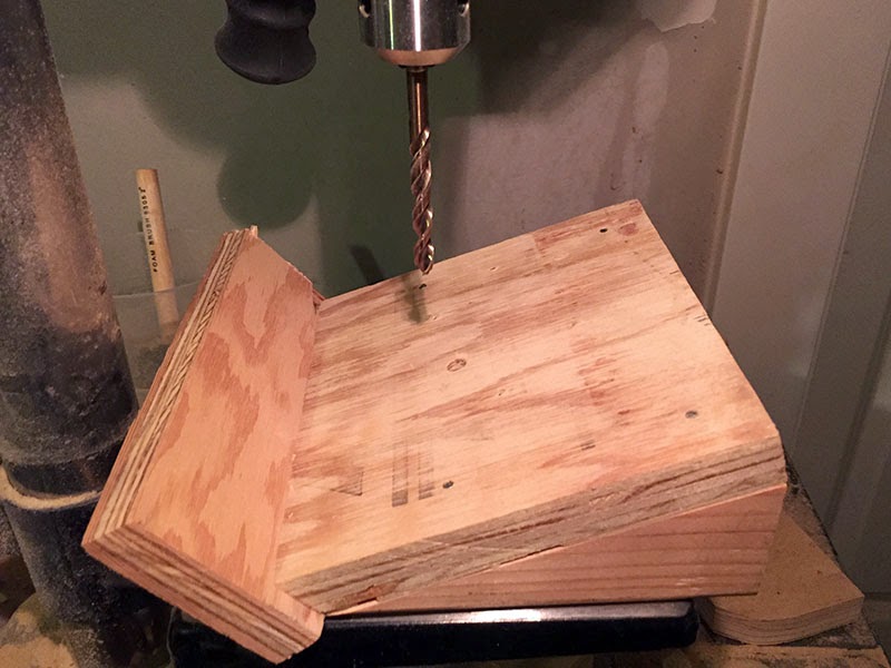
Now that I had all four holes drilled and lined up, I set to work creating a 20° jig for drilling the bolt holes.  These need to be parallel in relation to the top and bottom of the gunboxes.  Some quick work with scrap 2x4s (from when I mounted the wheels to the fender), the table saw, a hammer, and some nails, and I had a nice jig.

When I drilled the bolt holes, I made sure to clamp the middle and back plates together so that the holes were evenly lined up.  After a bit of time, I had them all drilled, and added bolts to test the alignment.  I was worried that the the tightness of the corners nearest the shoulder walls would be tricky to allow the addition of the eventual wing nut, so I tried to keep that in mind when deciding where I wanted to drill.  All these angles were making my head hurt!  I did a quick test to see if the wing nut had enough room to spin, and it indeed did.  Whew!

Since the middle plate is going to be attached to the back of the gunbox with wood screws, it needs to sit flush against it.  The bolt heads currently prevented that from happening, so a little countersinking was in order.  Switching to a forstner bit and using my jig, I added the proper countersink to each of the bolt holes.

I also switch to a small countersink bit and drilled (not at a 20° angle this time) the holes that the wood screws will use for attaching the middle plate to the interior of the gunbox (not pictured).


Now that everything was cut, trimmed, and drilled, I spritzed the pieces with my PVA wash (4 parts water, 1 part Titebond III) and waited for it to dry.  Since these pieces are going to be inside, they'll be exposed to water vapor from my breath, so I decided to seal them up before eventually painting and installing them.

Once dry, I re-added the bolts, springs, and wing nuts.  I haven't installed them inside the shoulders yet, as I want to prime and paint them (and the rest of the shoulder interior), which will come later.  Once painted, I'll attach a soft felt lining so that the globes don't get scraped when the gun or plunger arm are moved about.  Then they will be installed into the shoulder section.  Until then, they are resting comfortably in the same box where I keep my shoulder slats.

(As an aside, while I waited for the PVA wash to dry, I shopped for some proper exterior bolts to eventually attach to the fender, eye piece, dome cowl, dome lights, and gunbox details.  I was having a hard time converting the metric description of the bolts to what's available in the US, until I ran across acrodrome's post in the "2005 Design Dalek Appendages" forum.)

Sunday, September 21, 2014

Day 93 - Cutting bits for eyestalk and plunger arm

Wow, it's been a month since I last posted!  I feel neglectful!  Part of it is that I'm in a weird phase where I'm losing confidence in the build, and most of it has to do with the bloody dome cowl.

ChristmasDalek did as best as she could removing all the stuck-on linoleum remnants and other crud, but it's still a pretty nasty, crinkly mess inside.  So I just put it (and Rainier) out of my mind for awhile and sulked.

But, I'm trying to muscle my way through the funk.  I cleaned up the garage (which was one MAJOR thing that was keeping me from continuing), and that helped a lot.  The after shot should speak volumes.  No, I'm not a hoarder.  (At least I hope not!)

Now that my tools were back in reach with elbow room to spare, I set about on something else entirely (eschewing the cowl for now).  I decided it was high time to cut up all my aluminum tubing that I've had laying about.

First I set to work on the various pieces for the eyestalk, per the manual.  Now I need to get the eyestalk lenses cut to size and drilled.

Then I cut up the large plunger tube so that I had 20cm sticking out the back end for me to grab.  This matches what's currently the inner length of the gun tube, but I may trim both down if they prove too awkward for me to wield once I'm situated snugly inside.  From the front of the globe, 39.5cm of tube protrudes, per the manual.  For now, I also cut up the two smaller tubes to approximately the same lengths.  I'll be using 1" diameter acrylic hose as a means to extend the arm rather than longer lengths of tube, for safety's sake.

I can't remember if I mentioned it earlier in this diary or not, but the same friend who micro-lathed my gun bosses also carved me up some top hat bushings that I designed one day in Goggle Sketch-Up for my plunger arm tubes.  I've been keeping them in my freezer for months (thermodynamics and all that) and finally attached them to the cut up tubes.
On each of the inner tubes, I temporarily affixed masking tape 20cm from the top as a means to stop them from falling completely out of their respective housings.  Here's a shot of Rainier with his new arm fully extended!  Note the screw in the front bushing; a similar screw will be set within the eventual rubber-casted plungers that I'll be making.  Then, they can simply be screwed on to the arm!

That's all for now ... perhaps I'll try and fiberglass up the cowl soon after repairing some of the air pockets.  Or I may work on the eyestalk lenses ... we'll see!


Thursday, August 7, 2014

Day 92 - Removing the cowl mold

The next day, after work, I checked up on the progress of the dome mold.  It had hardened nicely, so I took it outside for removal.

It was attached pretty securely, so I used the same method to remove it from the dome as I had used to remove the dome from its mold: filler spreaders.  I lightly hammered several of them between the painter's tape and the dome, and eventually the cowl mold popped off.

What a sticky, nasty mess it was.  The spray adhesive was still wet and slimy, which made peeling off the linoleum strips quite a slick chore.  I removed most of it, but there were bits that I couldn't get to.

Additionally, the linoleum didn't behave like the plumber's rubber I used for the dome indentations.  In the case of the red plumber's rubber, the inserts peeled off the gel-coat with the greatest of ease (I even had forgotten to use release agent on them).  With the linoleum, it started to separate from itself, leaving bits stuck to the gel-coat.  The rippling effect is very prominent, as well, but I'm not too concerned with that.  Once I made a cowl from this mold, I'll just sand that down before priming.

Also, I couldn't easily get to the bits of balsa wood I used for the top "lip" portion of the cowl.  They're stuck in there pretty tightly.  ChristmasDalek has generously offered to clean up the cowl with her set of specialized picks and knives, and I'm very grateful for that.  We met to have lunch recently, and I passed the mold onto her.

So that's all the news that's fit to print at the moment.

Monday, July 28, 2014

Day 89 through 91 - Glassing up the dome cowl plug

I found some stuff called Bondo Bumper and Flexible Part Repair, which is a rubbery version of Bondo spot filler.  It also uses a catalyst to activate it, but they are used in equal parts.  Then you smear it on.  Also, it smells like burning tires, yuck!  A few applications of this goop filled up the gaps between the linoleum pretty nicely.

After that cured—which was pretty quick—I took out the Minwax oil-based polyurethane varnish that I had also used to coat and seal my dome plug months ago.  I applied a couple of coats every 4-6 hours or so, around the time each coat got tacky.  Then I left it to dry overnight.  In the morning, I noticed that it was still tacky, so I left it sit while I was at work.  Still tacky.  After chatting with acrodrome, I learned that there was no area for the oils in the varnish to soak into, linoleum being non-porous.  I was thinking that I needed to clean the whole thing off with mineral spirits, or, worse, scrap it all and start over.  For the third time.  But then, the weather turned very sunny, and I left it out in the brilliance for several more hours.  It finally cured!

(In hindsight, I probably didn't even need to do this step.  I remember when I had applied the rubber panels during my second dome attempt, and had neglected to even spray release agent into them, and they turned out just fine in the end.  Rubber and gel-coat seem to work well together.)

So, after that, I sprayed it down with silicone release agent and mixed up a small batch of gel-coat with some dye in it.  I added the catalyst, stirred, and sponged it on pretty liberally.  And, after a few minutes from finishing up, those weird chemical reactions happened again, like what happened when I was making the dome plug months ago.  So strange.  I wonder if it's the Minwax that somehow causes it.

While that was getting nice and tacky, I tore off some pieces of surfacing veil and chop mat from their respective rolls.  I was really hoping that I wouldn't run into a problem with air bubbles given all the sharp angles.  It was starting to get darker outside, so I didn't let the gel-coat get as tacky as I would have normally wanted it.

I spent most of the early evening and night applying the glass—two layers of the surfacing veil, and two layers of the chop mat (give or take).  I tried to work out the air bubbles as much as possible, and give good coverage to the cowl plug (especially on the sharp corners).  I put it back in the garage, turned on the heater, and left it to sit for another 24 hours.

I guess we'll see how it turns out tomorrow!  *crosses fingers*