Monday, January 12, 2015

Day 107 and 108 - Dome work, eye, and plunger

This weekend was a pretty fruitful one, being able to get a good chunk of time dedicated to some detailed areas.

I finally attached the bottom rotation plate onto the neck section.  I evened out the distances of each of the eight struts by measuring the distance from the top of the strut to the top of the upper ring.  There were only millimeters of difference there, so I marked the length of the shortest one on each that were taller than it.  After sanding the rest down to that length, I measured the length of the diameter between each pair of struts.  If I recall correctly, it was something like 46cm and some change.  I took one of the smaller off-cut circles of 3/4" MDF from the initial ring creation (back on day 19; my goodness, time flies) and routed the edge down little by little to match that length.

I was trying to factor in eventual dome rotation mechanics while doing this.  Since my struts were already pretty tall, I decided to cut notches into the plate and attach it to the strut sides instead of directly to the top.  If the plate were attached too high, the added distance of the second plate—along with the diameter of the rotation wheels—would exceed the proper distance between the bottom of the dome and the upper ring.  To prove this to myself, I sat what will eventually be the top rotation plate (the largest of the off-cut ring circles on top, with some spacers representing the distance of the wheels/bearings.  Then I placed the dome on top.  Sure enough, I should be able to get the proper distance by just routing away the outer edge of the top plate, millimeter by millimeter, the way AdamSt did.

I'll cut the inner section of the plate out later once I figure out some other stuff.  For example, I'm not sure which method I want for electric dome rotation (there are so many options that come up when searching the forums).  This will determine which plate I mount the wheels, place the motor, etc.  I don't know what any of that looks like at this point.

Now that I had the cowl in place on the dome, I could start to measure out where to place the eye pivot slot.  I knew that I wasn't going to be exactly centered—but at least pretty close—so I needed to wait to make sure that when eventually fitted the eye pivot is clear of the hole edges, and that the eyestalk clears the sides of the cowl when being moved up and down.  After a combination of relative measurements and eyeballing, and eventually marked out where the slot should be cut.

Problem was, I initially only made it 10cm instead of 14cm, and was quite confused when it proved to be such a tight fit for the pivot.  But I managed to get a couple cool photos anyway before correcting it and cutting out the extra 4cm.

Next, I turned my attention finally attaching the bushings to the aluminum plunger tubes with epoxy.  I used a product called JB Weld, which seems to be a recommended brand.  I used their strongest bond, one that sets in like a day, rather than their quick-bond stuff.

I cleaned all the tubes with 1000 grit sandpaper and Brasso metal cleaner to get them nice and shiny.  I then took a series of photos to make sure that I assembled everything in the correct order before attaching the bushings with the epoxy, because once those are on, they are not coming off without a serious fight (and probably major damage).  The acrylic hose barely fit inside the rear outer tube bushing, so I roughed up the surface of the hose a bit with coarse sandpaper.  But I ran into another problem almost immediately: once I had pushed the coupler into the hose, it expanded the circumference of the hose a fair amount, making it impossible for the bushing to fit around it.  If I had the presence of mind, I would have simply slid the bushing on from the back end of the hose (duh!), but instead, I attached a sanding burr to my Dremel and whittled the hose wall down until the bushing could fit!  What a silly person, me.

I mixed some batches of epoxy, gobbed it onto both the bushing wall and the interior wall of the tubes, pounded everything into place with a rubber mallet, and set it all out to cure overnight.

The next day, the were all completely cured and looking very solid.  I attached the (incomplete) plunger to the front, and snapped a couple more pics of it extended and retracted via the acrylic hose.  Soon, I will add black felt to the gunbox hole chamfers and mount both the gun and the plunger arm with my gunbox mounts.

Since I was working with the aluminum tubing, I decided to take an off-cut of the 1" tube and make an axle for my eyestalk pivot.  On the pivot itself, I noticed that the two-part Gorilla glue attaching the plastic outer skin to the MDF disk is coming loose, so I may need to re-glue it.  Also, the two pieces of 1/2" MDF seem to have detached from each other.  If they fall apart completely, JB Weld might be the answer!  Anyway, I slid the tube into the pre-drilled center hole and made a 5/8" hole using the pivot hole itself as a guide.  Once done, I sanded out the new tube holes a bit so that the threaded lamp rod could easily pass through.  For now, it's temporarily mounted inside the dome just to keep it somewhere out of the way (and to make Rainier look terribly awesome at the same time.)

As the weekend was wrapping up, I finally got around to sanding all the excess ABS glue that had hardened around the seams of the eye section.  Sanding ABS plastic isn't all that different than sanding wood, but I sure hated losing that smooth shine.  Ah well, it will be all smooth again once primed and painted black.  And, now that it was sanded (and then smoothed a bit more with a finer grain), I added the twelve 2.5cm "lugs".  These were cut from Plastruct half-round styrene rods that I had previously ordered with all my other plastic parts.  I initially used Krazy glue to secure them into place, and then ran a bead of acrylic cement to really bond them into place.

Then, for my final detail, I drilled the three holes for the eye piece bolts.  There doesn't seem to be an "official" distance for those holes to be drilled from the rim of the eye, so I measured a length that didn't appear to be too fragile—1cm from the rim seemed fine.  I used a bit more JB Weld to also secure some nuts to the interior for the bolts to be threaded into.  When I got up the following morning, I made sure to take my pliers to remove the bolts form the semi-cured nuts lest they be permanently cemented together!  It seems like that solution worked really well, and I'm quite happy with the results.


Sunday, January 4, 2015

Day 106 - Cowl 2.0 demolding

Today, I spent most of the day's daleking demolding and working on the cowl.  I took special care not to damage this second cowl attempt, unlike the first one.  I added a number of slender wooden stir sticks all around the mold to separate everything evenly, instead of slamming wedge after wedge of thick plastic spreaders and risk warping and cracking the part.

Despite the fact that multiple pulls are supposed to get easier, I managed to literally "break the mold" this time!  I don't think the mold is beyond salvaging; however, it would be wise to just make a brand new mold from a nice, cleaned-up fiberglass cowl.  That is if I ever feel the need to explore this damnable part of Rainier ever, EVER again!  This is the last bit of fiberglassing I needed to do, and for the foreseeable future, I am done working with that itchy stuff!  I'll still be using resin for a couple things, but no more glass fabric!  (Maybe.)

The cowl took quite a while to separate from the mold, but eventually, it did come loose.  The name tag inset made with the cut-up PAX badge came off with it, but it was easy enough to remove, carefully, with a razor blade.  I trimmed most of the fiberglass "fur" off of it with scissors.

I spent the next couple of hours using 80-grit sandpaper to even out all the ripples, bumps, and uneven surfaces.  I haven't yet done this step with the dome; it still has all its unevenness and such.  But the work on the cowl gave me confidence when I get round to sanding the dome.  Much of the gel-coat came off, which is why it looks so patchy in its current state, but once sanded smoother and primed, it should look great.

I was especially proud with how even the multiple layers of fiberglass and resin turned out to be.  I intentionally made the parts that were meant to be cut out much thinner than the rest of the cowl, so that my Dremel tool would pass through all that nicely and easily.  The rest was quite thick and sturdy.  There now appears to be a uniform thickness to the interior walls of the cowl where the eyestalk will eventually protrude.

I was completely covered in fiberglass and gel-coat dust by this point, so I also spent some time sanding the underside edges of the cowl so that it would lay as flat as possible on the dome.  Once done, I carefully aligned the position of the cowl on the dome and used my calipers to make sure the top was centered and that the right and left sides were evenly spaced from the front dome insets.  I used the calipers once more to determine a nice, secure, symmetrical place in which to place the four bolt holes so that the wouldn't be too near the edges (to prevent accidental cracking).

I used a 1/4" forstner bit in my hand drill to make the holes in the cowl first.  Then, holding it in place on the dome, made the first hole I've drilled into the cowl.  I was a nervous wreck (never having marred the dome before now), yet I managed to drill a corresponding hole into the dome.  I pushed one of my 1/4-28 steel button head screws through both the cowl and the dome, and made a pivot by which I could align the other three in place.  Before long, all four bolts were in place.

There were a couple of air bubbles on the cowl that revealed themselves during the sanding process, so I just need to do a bit of Bondo work to clean up the rest of it, and also to smooth out the front a bit more.  Then it will be ready for its eventual paint job.

(I also made plunger number 7.)

Tuesday, December 30, 2014

Day 104 and 105 - Recasting the plungers and making cowl 2.0

I got my Polytek A70 rubber in the mail, and set to work on recasting the plunger.  This stuff is so much different than the A30!  It's still a two-parts-in-equal-measure substance, but the pour time is only five minutes (as opposed to 30), and the demolding time is only an hour (instead of 18 hours)!

Once the first one had been released from the mold, I turned around and made five more that day.  I've got six plungers in all, and a whole lot more of the stuff left!  I'm debating on using it all, and that would net me about—at rough guess—18 plungers or so, since
I've only gone through about a third of the two bottles.

(I've since discovered that two of them have one small air bubble each in the cup portion, but they're hardly noticeable, and I will probably just cover them with a few permanent marker penstrokes.)

In the meantime, the A30 plunger has all but fallen completely apart.  Poor thing.

Then I set to work on my second attempt at the dome cowl.  I had again pre-cut my fiberglass pieces for the first layer (to make sure all the angles were shape to mitigate air bubbles), and then planned on using surfacing veil for the second layer, and thicker ripped-up chop mat for the third and potential fourth layer.

I got out the dome cowl mold and washed it.  Having neglected to add the name tag indentation on my first attempt with the cowl, I corrected that this time.  I took an old plastic convention entry badge (PAX, for those who are curious), cut two 7.5cm x 3cm rectangles out of it, and cementing them together with carpet adhesive, clamped for a nice amount of time.  Then, I sprayed a lesser-grade adhesive (the one I used for the rubber dome inserts) onto one side, let that get tacky, and clamped it onto the cowl mold for about an hour.

I coated the mold with a sponged-on layer of PVA (left to dry), and then a few passes of silicone release agent spray.  No wax this time.  My leftover can of gel-coat had set in its tin since the time I had last cast a cowl, so I needed to go get another one, grumble, mutter.

With the fresh tin in hand, I stirred it all up so that it wasn't all settled and separated.  Then I poured myself five ounces or so in a separate pot, added the catalyst, and stirred, stirred, stirred.  I sponged all that on (with about an ounce left over), and let it sit for two hours with the heater on in the garage.

Once it was mostly dry, I placed the pre-cut pieces into position and mixed up about four ounces of resin.  Once those pieces were in place, I added a layer of surfacing veil glass over the top, ensuring that I had taken care of any visible air bubbles.  I took about an hour break, and then tackled the next layers of chop mat, mixing up six more ounces of resin for that.

All in all, I think this one will turn out much better than the first.  I'm still going to need to do a lot of repair work on it to smooth it all out due to the rough, ripply texture of the mold, but hey, that's what Bondo and sandpaper are for.

I'll get this Dalek done if it kills me!  (Or rather, unless it kills me!)

Monday, December 15, 2014

Day 101 through 103: Floppy plunger time!

This will hopefully be an informative yet amusing post.  So, where did we leave off?  Oh yes, I had made a plunger master mold out of ABS plastic and PVC pipe.  Let's show the kiddies what I did with it!

I was very inspired by chrisosborne's post about making a two-part silicone mold for the plunger, but I didn't want to build a mold box out of acrylic sheets.  I looked around on the web for alternatives, and after perusing a few YouTube videos on the subject, I decided to build one out of Lego bricks.

Keeping this mold exactly centered was very important to me, as I wanted the final rubber plunger to have a uniform wall thickness (the thinnest part of the plunger only being 1/8" thick).  The main advantage of having a Lego mold box, according to my thinking, was that all the Lego studs would keep everything very much in center.  I used a forstner bit to drill a hole in one of my sacrificial Lego bricks (*gasp!*) to center the PVC portion of the plunger.

For the bottom of the mold box, I made an extra reservoir space with a grilled floor.  This would force the cured bottom mold to be perfectly in place and not move around, again ensuring the centering of the final piece.

To keep the plunger master mold in place, and to prevent silicone from seeping into the inner cup, I filled the plunger bowl with plasticine putty.  When I placed the master mold back into the mold box and centered it, it stayed put.

(Not pictured is the event known as the "cup overfloweth", where I lost about $75 worth of leaked silicone when I tried to mold the bottom part first without making sure things were sealed.  Lego like to come apart when weight is placed on them.  Who knew?)

Next up was to mix up a batch of the silicone (I used something called a Squirrel mixer, which caused me no end of amusement, ah, the visuals) and whipped up a bunch of blue goop in no time.  It has a nice 30-minute pour time, too.  I placed the mold box on the floor, and from about three feet up, I poured the silicone in a very thin bead to reduce air bubbles.  After a few long minutes, I was done and the mold was filled.  Now I just had to let it set for 24 hours.

A day later, I checked on the mold and the silicone was nice and firm.  I took the bottom part off and cleaned out all the putty, wiping off any remaining smudges of it with paper towels and a microfiber cloth.  I placed the bottom of the mold box back on, prepare more liquid silicone, and fill in the bottom part of the mold.  And then wait another 24 hours.

When the other half of the mold was ready, I removed the whole lego enclosure and looked at my handiwork.  I had two wonderful halves of the plunger mold, complete with alignment keys and perfectly centered.  The man at TAP Plastics told me that nothing sticks to silicone like more silicone, so I used some release wax and an oil-based agent (called Pam cooking spray) on the mold interior.  I was thrilled to mix up a batch of black rubber and get to work!

I modified the Lego box a bit by only using a few rows of bricks around where the two mold pieces meet, to prevent leakage.  In the center of each side, I built pillars all the way to the top of the mold to lay a jig, which would be used to suspend and center a bolt within the plunger stem.  This would then screw in the plunger to its arm bushing.  I destroyed another sacrificial lego by drilling a centered 1/4" hole for the bolt.  I then mixed up some of the two-part rubber and added the black pigment to it (note that it says "shore A-30" on the bottles, this will be important).  This mixed very thinly, so I needed to slap a bit of the plasticine clay onto the Lego to prevent leakage.

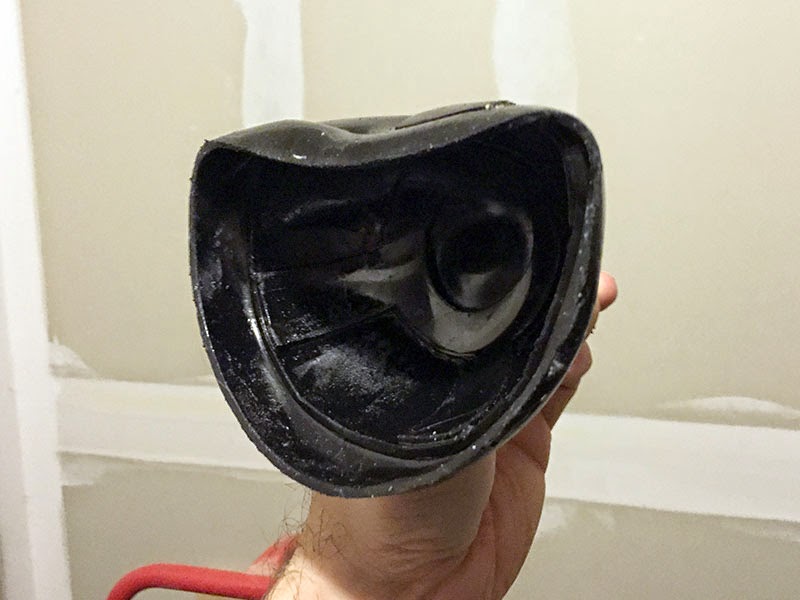
After about 18 hours or so, it was time to demold the plunger.  I was very excited!  The bottom mold popped off easily enough, and before too long I managed to get the top part off, too!  And then I held my plunger to the light, and it ... started ... to ... droop.  And there were weird and bumps on its surface.  The drooping, I later found, was due to the shore number (remember A-30?).  A-30 is softer than a pencil eraser (which is A-40).  A-70 is about the strength of a car tire.  A-85 is a wheel on an inline skate.  TAP Plastics doesn't carry anything beyond A-30, since they're selling mold-making materials.

So, again, I referred to chrisosborne's post, and saw that he ordered A-70 rubber, which I promptly went online and ordered, too, from the very same store!  It hasn't come in yet, but when it does, you'll be the first to know how it goes!  (Well, after me, obviously.)

As far as the pits and blemishes, I can only assume that the TAP Plastics guy was wrong about the vegetable oil.  I think it reacted to the liquid rubber and made things kinda weird, chemically.  The plunger is still a bit tacky (bits of rubber fall off when a finger rubs it) even after several days, now.  ChristmasDalek expressed a potential interest in it, but I'm not sure its ability to survive in our harsh world.


Thursday, December 4, 2014

Day 100 - Eyestalk pivot and plunder plug assembly

Although I've been working on Rainier since July of 2013, this marks day 100 of active work on him!  So, I wanted to post something iconic: the completed eyestalk and the plunger!

My previous attempt at making the eyestalk pivot wasn't too successful, as I had neglected to make sure that the circular pieces of MDF and HDF were all lined up perfectly when I glued them together.  I found, after sanding them, that there was a slight angular tilt instead of a perfect cylindrical piece.  Because of this unevenness (and the fact that it was already cut in a circular shape), it was very difficult to drill a shallow hole where the eyestalk tube would be inset.

I mulled over in my mind how else I wanted to approach this.  What I decided to do was to take larger rectangular pieces of MDF and HDF—cut to the same size and squared on the table saw—and glue those together as before.  Once the glue had set, I marked off the square I wanted to work with, found center, and drilled the shallow where the eyestalk rod would be inset.  I also took the opportunity to drill the centered 3/8" hole for the lamp rod to pass through.  Then I took the 4" circular saw blade to it, and cut out the circle.

To solve the issue of how the lamp rod and axle rod would meet, I decided I would use my leftover 1" aluminum tubing for the axle.  Using the same 1" forstner bit, I drilled a hole all the way through the center of the pivot on its side, then test-fitted the tubing.  When I get ready to fit the lamp rod, I will simply use the eyestalk pivot itself as a jig to drill the 3/8" holes through the aluminum tube.

The outside diameter of the saw is 4", which means that the resulting piece is shy of that by about an 1/8".  Using some of the 4" Plastruct ABS tube I bought for the eyeball, I measured and sliced off a section and clamped it on with a two-part epoxy glue.  Once that had set, I carefully drilled (starting small and working my way up with larger and larger bits) the eyestalk tube hole.

A nice advantage of having the ABS plastic on the outside was that I could now adhere the pivot strips.  I took a tip from Jon Place's build diary and used zip ties.  I couldn't find ones that were flat; the only ones I could find had a texture on them, but I actually quite like it.  It compliments the more industrial look of the NSD-type daleks in my opinion.  One problem with the plastic these ties were made from, however: it basically ignores my acrylic cement.  So, what I used instead was simple super glue.  To space the strips evenly, I used a blade from my jigsaw.  Afterward, just for kicks, I ran a bead of acrylic cement along each space, let that set for a bit, and then took an X-acto knife to trim off the excess.

I carefully trimmed the zip ties along the inset hole and test-fitted the eyestalk tubing.  It was a very nice fit, so I assembled the eyestalk with the new pivot, and am very pleased with the result.  It is now set aside for eventual sanding and painting, not to mention the electronics.

Moving onto the plunger, I followed lochsloy's method of measuring out and cutting the inner and outer Plastruct cup parts.  For removing these sections, I used my Dremel tool for the major work and some 80-grit sandpaper for fine-tuning.  I switched to finer and finer grits to polish it off.

The part of the plunger that had me confused the most was the outer flare.  In lochsloy's diary, he leaves the part as-is, only sawing away the hole for attaching it to the plunger.  In screenshots and prop photos that I've seen, the outer flare seems to be trimmed quite a bit.  My decision was to leave it as-is, and when I cast the eventual rubber plungers, either trim it down with an X-acto knife or just leave it alone.  What I did have to do, however, was cut back the four outer ribs by about an 1/8" so that I could attach the flared rim to the outer bottom part of the middle plunger cup.

Attaching everything together was done by using the same acrylic cement I used for assembling the light cages.  I didn't need to use melted ABS glue as I did for the eyeball, since this is intended to just be a plug for an eventual silicon mold.  I also took some two-part epoxy glue and attached a measured length of 3/4" PVC pipe for the stem.  This will then fit in nicely with my 1" tubing I will be making the "hard" back section of the plunger out of.

And there we have it!  Next up: making the silicon mold of the plunger!

Sunday, November 16, 2014

Day 99 - Neck bin mesh

The cold weather is preventing me from working on dome cowl 2.0, so I decided to return to work on Rainier by crafting the mesh segments for the neck section.  This was very exciting for me, as I've had the material components for this for quite some time, just sitting in their boxes.

First thing first, I needed a template to account for the curvature of the interior of the neck section.  Taking some leftover scrap cardstock from when I measured out the shoulder section cladding, I placed it inside the neck and traced out and cut a few quick lines.  I checked this single template on each of the eight interior sections of the neck, just to make sure the measurements were accurate all the way round, in case the neck was a little lopsided.

The template was a good fit for each section, so I used it to trace an outline on the eight aluminum BBQ grills I had stored away.  I took my Dremel tool and carefully cut out each of the aluminum sections with a metal cutting blade.  The speed of the blade coupled with the delicate nature of the grills meant that a few of the aluminum "tines" were a little bent, so I took some pliers and straightened them back into their "V" positions.

Taking the black voile cloth out of its box, I cut out several oversized square pieces with scissors.  The cloth was a bit wrinkly from being stored away for so long, so I stacked the squares on top of each other, placed them between two towels, and ironed them out. (I didn't place the iron on them directly, as they are polyester and I didn't want the iron to burn them.)

At Lowe's, I found that Loctite made an aerosol carpet adhesive (stronger than the other adhesive I used for placing the rubber inserts into my dome mold), so I procured some and used it on the BBQ grills.  The instructions on the tin said that for a stronger hold, spray one layer and let it sit for 2-5 minutes, and then spray another layer on top of that.  I did just that, and then placed the black voile carefully onto each grill, gently smoothing it on with my hand.  I took a large spare board and covered the freshly-sprayed sections, applying some hefty weight to them (a combination of myself and my electric wheelchair batteries, somewhere around 200 pounds).  Then I played Bejeweled on my phone for 5 minutes.

After that, I took the board off.  I noticed that, similar to AdamSt's diary, the adhesive sprays in a spiderweb-like pattern, which would need to be cleaned up.  Rubbing the grill with the abrasive side of a standard kitchen sponge did the trick on that front.

I then trimmed off all the excess voile with scissors, and for an extra measure, very carefully burned off any frayed bits with a cigarette lighter.  All eight sections were finally complete!  I also had my Heronrib nearby, still in its box, so I cut out eight sections of that for eventual trimming.  I will trim them to shape once I'm ready to attach them to the neck section, which won't yet happen until it's sanded, primed, and painted.

Looking through the mesh, I finally have my first hint of what my obscured vision will be like inside Rainier!